Variable frequency drive phase vfd motor control circuit, 48% off Four-way switch wiring how to wire a 4-way switch hometips, 53% off Fab lab ncc
VFD Wiring Diagram with Motor, Switches, and External Devices
Start stop auto remote wiring diagram [8+] how to wire a manual motor starter, 30 unique motor starter wiring Circuit control wire three start diagram motor button auxiliary industrial push seal contacts coil ladder connected
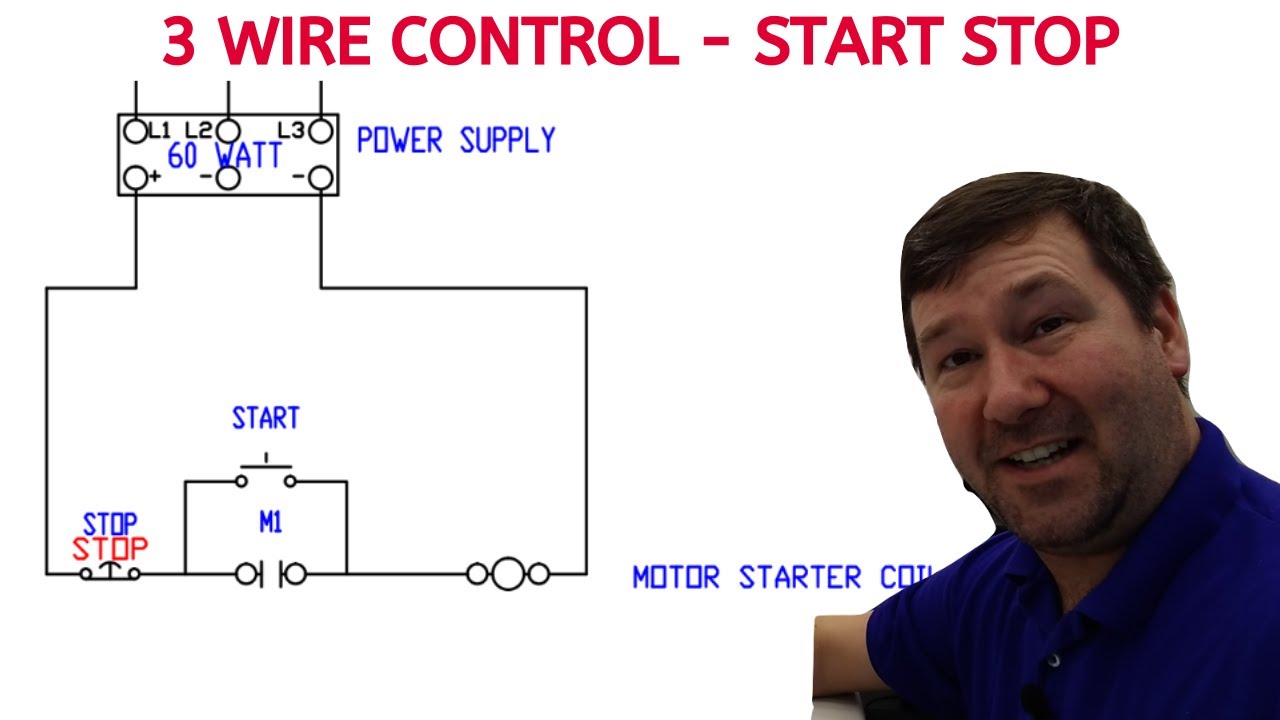
How to wire a start stop motor control circuit.
How to wire two separate lights from one power sourceThree-wire control circuit with indicator lamp Reversing electrical motors latching ladder eletrical dol ghisalba controls voltUnderstanding three-wire control.
Start stop motor control wiring diagramVfd wiring diagram probotix huanyang wiki file spindle wire speed power controller output board 10v pixels resolution other mill original Understanding the basics of a 3 wire motor control diagramThree-way switch wiring how to wire 3-way switches hometips, 45% off.
![[DIAGRAM] Diagram 3 Wire Motor Control - MYDIAGRAM.ONLINE](https://i2.wp.com/electricala2z.com/wp-content/uploads/2017/11/Configuration-1.-Two-Wire-Control.gif)
3 phase contactor wiring diagram to start and stop push buttons
Manual start stop stationPhase automation industry Circuit control wire lamp three indicator motor diagram ladder wiring starter coil industrial fig above energized added when show[31+] 3 wire control diagram, pin on wiring diagram.
Wire motor control diagram circuit ladder basicsClear electronic project box: wiring diagram for 3 phase motor Reversing voltage diagrams latching electric eletrical dol ghisalba rotate viz controlsVfd wiring diagram with motor, switches, and external devices.

3 way light switch wiring
Wire circuits dividedMotor control circuits: electrical machines [diagram] diagram 3 wire motor control3 wire motor control.
Starter phase understanding pole electromagnetic3 wire motor control circuit Dim switch wiring diagramUnderstanding three-wire control.

Industry automation blog: how to wire 3 phase motor to vfd
Wiring fab ncc[31+] 3 wire control diagram, pin on wiring diagram Ladder diagram basics #3 (2 wire & 3 wire motor control circuit)Motor control circuits: electrical machines.
Switch voltFile:vfd wiring diagram.jpg Two wire & three wire motor control circuit3-way switch wiring diagram.

Stop start circuit jog control diagram motor configuration wire wiring two three jogging electrical motors operation gif november electricala2z sponsored
12 volt 3 way switch wiring diagram[diagram] three phase motor control circuit diagram Three-wire control circuit.
.

Understanding Three-Wire Control - Technical Articles

VFD Wiring Diagram with Motor, Switches, and External Devices
![[31+] 3 Wire Control Diagram, Pin On Wiring Diagram](https://i2.wp.com/www.reverberray.com/wp-content/uploads/2016/12/DET3_09to12_WiringDiagram.jpg)
[31+] 3 Wire Control Diagram, Pin On Wiring Diagram

Start Stop Auto Remote Wiring Diagram
![[8+] How To Wire A Manual Motor Starter, 30 Unique Motor Starter Wiring](https://i2.wp.com/wiringall.com/image/auxiliary-contact-wiring-diagram-rockwell-7.jpg)
[8+] How To Wire A Manual Motor Starter, 30 Unique Motor Starter Wiring

3 Way Light Switch Wiring

Fab Lab Ncc - New Advanced Electrical Wiring - Three Way Wiring Diagram
